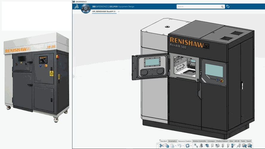
Create complex 3D Parts and Assemblies
Contains the application Part Design Essentials, which provides features such as Boolean operations. Choose between single-part sketching and working in the assembly context, and integrate multiple product views and constraints. EMR allows users to quickly compose assemblies and position parts. Powerful tools pattern and symmetrize parts, and manage the assembly-level impact of functional features such as holes. Clear specification management tools let you make modifications and quickly assess their impact – ideal for multi-user environments and productive iterations.
Design and manage product structure
Includes Product Structure Design; a set of capabilities that allows engineers to both design and manage the assembly structure. It supports change management and collaboration.
Automatically generate 2D drawings with 3D definition
Drafting tools automatically generate drawings from the 3D master definition. It reduces the cost of producing 2D drawings and ensures that they are consistent with the 3D digital definition. Automatic updates ensure that the 2D and 3D are in-step with one another.
Create complex surfaces
Generative Wireframe & Surface functionality provides an extensive set of tools for creating and modifying mechanical surfaces for complex shapes or hybrid parts.
Capture and reuse templates
Capture geometrical design and know-how through 3D Templates Capture, which allows engineers to share best practices and avoid duplication of effort. Engineering Templates Reuse capitalizes on existing knowhow to save time and let users focus on innovation.
Create and validate kinematic models of manufacturing devices
Provides a collection of easy-to-use tools for the creation of both forward and inverse kinematic devices. Appropriate kinematic solvers are automatically assigned for revolute, prismatic, and other types of kinematic joints. Using a library of mathematical operators, users can easily create equations when modeling advanced devices. They can jog individual joints or move the device’s Tool Center Point in 3D to validate the kinematic definition. Once the kinematics are defined, EMR has the unique capability to store the mapping of the kinematics in a template. This color-based mapping allows other users to apply the same kinematics to other mechanisms of the same type, with just a couple clicks. Machines are built either as a single controlled mechanical device, or as a group of devices being controlled as one to simulate the most complex machines.
Assign inverse kinematics to manufacturing devices
The inverse kinematics functionality allows devices to be driven by commanding Tool Center Point positions instead of device joint positions. EMR provides support for automatic inverse kinematics solvers, generic and numeric, as well as device-specific solvers for industrial machines based on manufacturer specifications. EMR also supports user-defined solvers for custom-made robots to allow users to define the inverse kinematic algorithm for special or experimental machines, and NC machines with fixed or moving beds, rotary axes on a bed or head, and interchangeable heads, as well as mill-turn machines with rotary and mill turrets.
Define home positions and joint travel limits
Define joint values that correspond to states or home positions of the machine for use in manufacturing simulation. Joint travel limits and soft limits let users specify range of motion for validation during simulation. For programming advanced mechanisms, the range of motion can be defined as a formula based on other joint values of the device. Modeling NC machines supports multiple tool change positions, including the position’s axis priorities. NC machine table and spindle positions can be defined by identifying the tool and workpiece mount parts & axis systems.
Define motion controllers and manage motion groups
Define both motion controllers and motion groups. Motion controllers allow the end users to specify the grouping of different kinematic devices and the associated behavior. This enables the coordinated motion of resources. An example would be a robot, a mounted weld gun, and an external positioning table working in tandem in a spot-welding scenario. A new interface allows users to better create and manage motion groups in complex scenarios.
Customize controller attributes through profiles
Define preset controller settings for tools, motion, and accuracy for manufacturing devices with inverse kinematics, such as industrial robots. These profiles allow the manufacturing resource to switch the device controller settings during simulation. It is also possible for users to define their own profile schemas. These profiles can be associated with instructions in the robot program that are downloaded with the program as part of the off-line programming translation.
On–the–Go (Offline Mode)
Disconnect from the 3DEXPERIENCE®platform for up to 30 days. Once disconnected, the user can create geometry and assembly structure, and simulate devices. Home Positions, Tasks and Profiles as well as other features can be created and edited offline. Upon reconnecting, automatic data reconciliation will ensure that changes are preserved in the database.
Machine & Tooling Designer (EMR-OC)