Redesign and simulations for robotic arm for Inmold company
Solfins Engineering simulations services for Inmold company
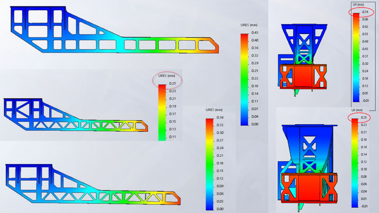
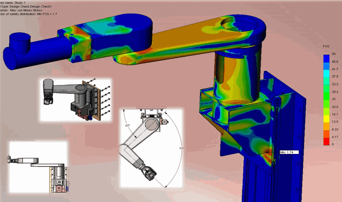
reducing robotic arm weight for 10 kilograms
~20% mass reduction
simulation value 0,74 ~ physical part in machine measurement 0,8
Calculation and optimization of robotic manipulators
Device built
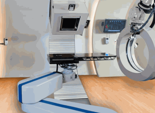
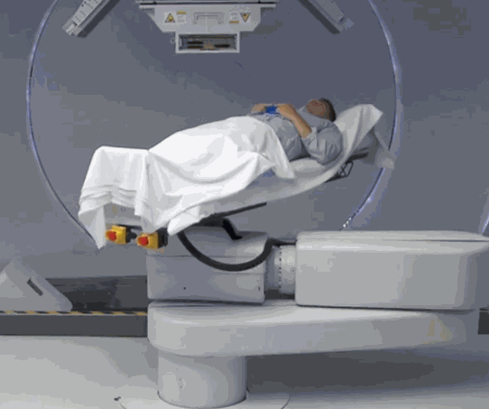
A robotic arm with a patient bed. The arm synchronizes with the upper proton cannon which actually treats the patient and destroys the cancerous tissue.
Device built
It is very important that the deformation of the robotic arm and the upper proton cannon be small and that it is possible to precisely hit and destroy the bad cells in the tissue affected by the tumor, without destroying healthy tissue.
Proton cannon design and optimization
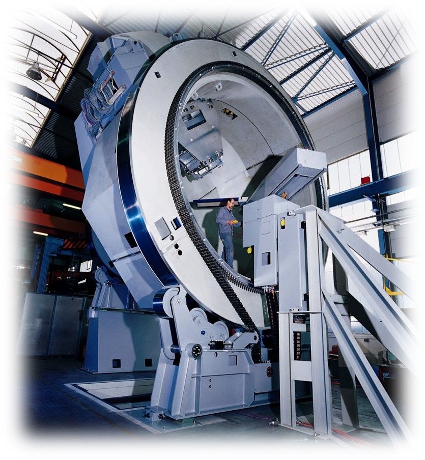
Subsystem design and proton cannon optimization for the treatment of patients with tumors
The whole construction
weighed over 200 tons, which is equal to the weight of the Statue of Liberty!
The construction revolves around the patient and is supported by rollers whose
expected working life should be over 10 years without downtime. Extremely heavy
magnets are mounted on the construction, the position of which must be kept within
narrow tolerances in order for the function of the device to be correct. The
key part of the calculation was keeping the deflection within tolerances.
A project like this could not be completed using just manual calculations, experience, or intuition. We certainly didn't have experience, but we had guts and expert knowledge of the SolidWorks Simulation tool; utilizing these, we successfully completed the project. The device has been working successfully for years and, so far, we have not received any feedback that something was wrong, even though we were asked to dimension key components with a service life longer than 10 years :)
3D model
Magnets are shown in blue, each of which weighs several tons. To the right is a cantilever overhang that was critical in terms of deformation. On the left side, you can see a large wheel with a diameter of over 4 meters, which rotates on rollers, whose lifespan was uncertain due to the possible occurrence of material fatigue. The entire structure rotates several times for one patient treatment due to the transmission relationship between the large wheel and the rollers; the rollers themselves rotate a great number of times, therefore having a large number of sinusoidal loads. On the right side, we have a smaller wheel about 2 meters in diameter, which also rests on 6 rollers. Due to the size of the construction and inaccuracy of production, the geometry of the rollers was questionable. Therefore, the input requirement for the calculation was the analysis of the barrel shape and the optimal radius of the barrel roller which would give the longest service life.
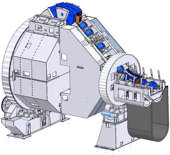
Calculation and report on the deformation of structures
Deformations of simple structures like beams are easily performed using our university knowledge. In the case of complex three-dimensional structures that are not symmetrical and are rotating around a certain axis, too many positions and calculation cases are created. Analyzing a structure like this is only made practical by using a simulation package like SolidWorks Simulation!
Calculation and report of working life
The essence of the Simulation Software is to design the service life of your machine parts. The construction should never be too good; rather, you want it to be good enough for the market and your customers. A good constructor is one whose parts will fail after the warranty period. This period should be predicted in the accompanying maintenance manual with a spare parts catalog, where a replacement cycle is suggested, and a spare parts business is provided for your company.
Design and calculations of manipulators for the automatic joining of drilling pipes on oil rigs
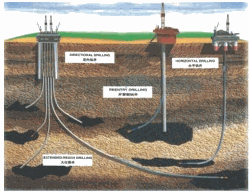
Project challenges
Oil is drilled by mounting a drilling tool on a 10m long pipe. When a 10m deep hole is drilled, the first pipe continues through the threaded joint to the second pipe and so on, up to several kilometers in depth. It is even possible to control and turn all the pipes in the row to create a tree-like system that draws oil from a wide area around the borehole.
Imagine if the threaded connection is not tightened to the required torque. What happens to the miles of pipes that remain trapped in the ground? One day of downtime which causes equipment stasis can cost $10,000 - 500,000 per day!
The entire drilling rig must be mobile and packed on a truck which brings the equipment to the drilling site. It then performs drilling that lasts 2-4 weeks and afterwards everything is re-packed on the truck and moved to a new drilling location. All equipment on the platform must therefore be mobile, light, and take up little space. The equipment must be able to work at -40 and +50 degrees Celsius.
The forces and torques to which the equipment is exposed are incredibly large; the pressures and forces created by the hydraulics are at the level of a few hundred bars. In addition, the equipment must be easy to service and have parts replaced both when it is -20 degrees outside and when operators are wearing thick work gloves!
In addition to the fact that we have so far participated in projects of a large number of subsystems used on oil platforms, the subject of this project is a device that fully automatically tightens the pipes to the required torque.
Imagine a 10 km deep hole, meaning one thousand 10m pipes: each should be twisted, and when the required depth is reached, each should be taken out and unscrewed. Then the whole procedure is repeated with a larger pipe diameter and a larger "cutter" due to huge torques. After that, 10 km of pipes (casing) are inserted into the drilled hole which are the diameter of the opening itself so that the wall of the hole does not collapse. All that painstaking work is done by our device, for which we received recognition as the most innovative solution in the American oil and gas industry in 2015.
Even though we previously didn't have a lot of experience in this industry, our innovation was enabled by simulations of each and every segment of the project!
Equipment buyers often want the wrench to be mounted on the different types of manipulators shown in the figures below.
Manipulator 1 - concept simulation
After sketching the basic concept, it is possible to check dimensions and working strokes, with calculations of the lever resistance and the sizing of the cylinders, engine and bearings.
Manipulator 2 - concept simulation
The Cartesian manipulator and starting concept, which was modified in its final version after intensive calculations and simulations. It is possible to add a center of gravity and mass to each block on the displayed sketches based on which sizing is then done.
Manipulator 3 - concept simulation
An abandoned conceptual model, which in the final performance is surpassed and replaced by a different device.
Manipulator - additional simulations at a later stage with an updated weight estimate
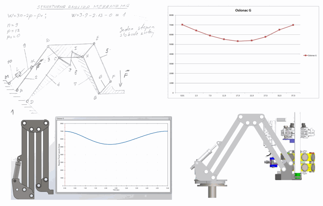
Manipulator - checking simulation results in SolidWorks software and through manual calculation gives identical results and graphs
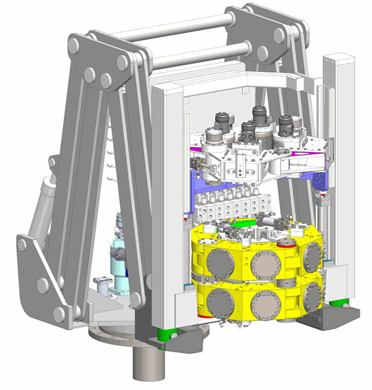
Model of a device
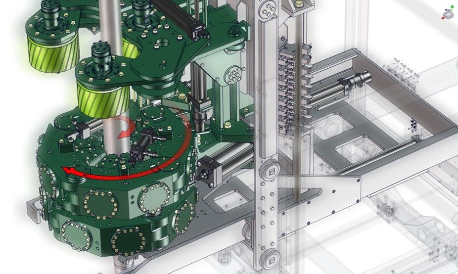
Model of a device
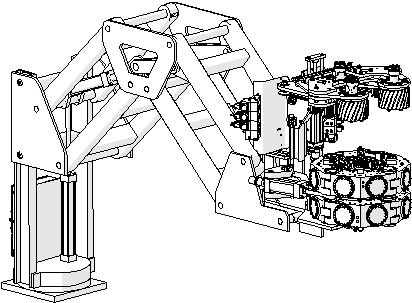
Manipulator 1
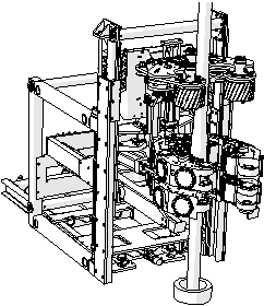
Manipulator 2
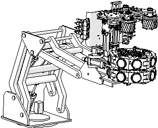
Manipulator 2
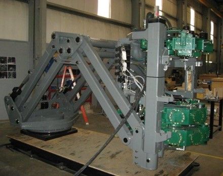
As built
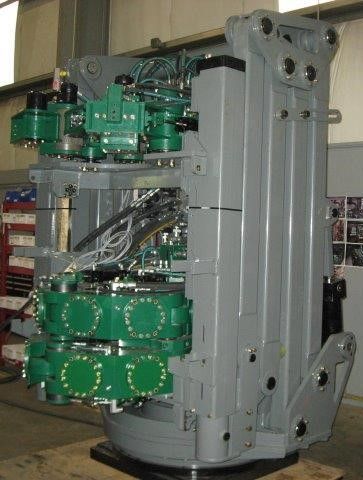
As built
calculations of all subsystems
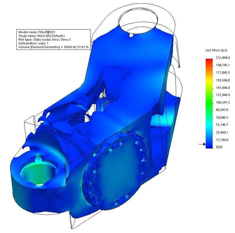
Segment of a torqueing device
There are two hydraulic cylinders within the casted block working at over 250 bars. Each of the cylinders generates a force of over 50,000 pounds.
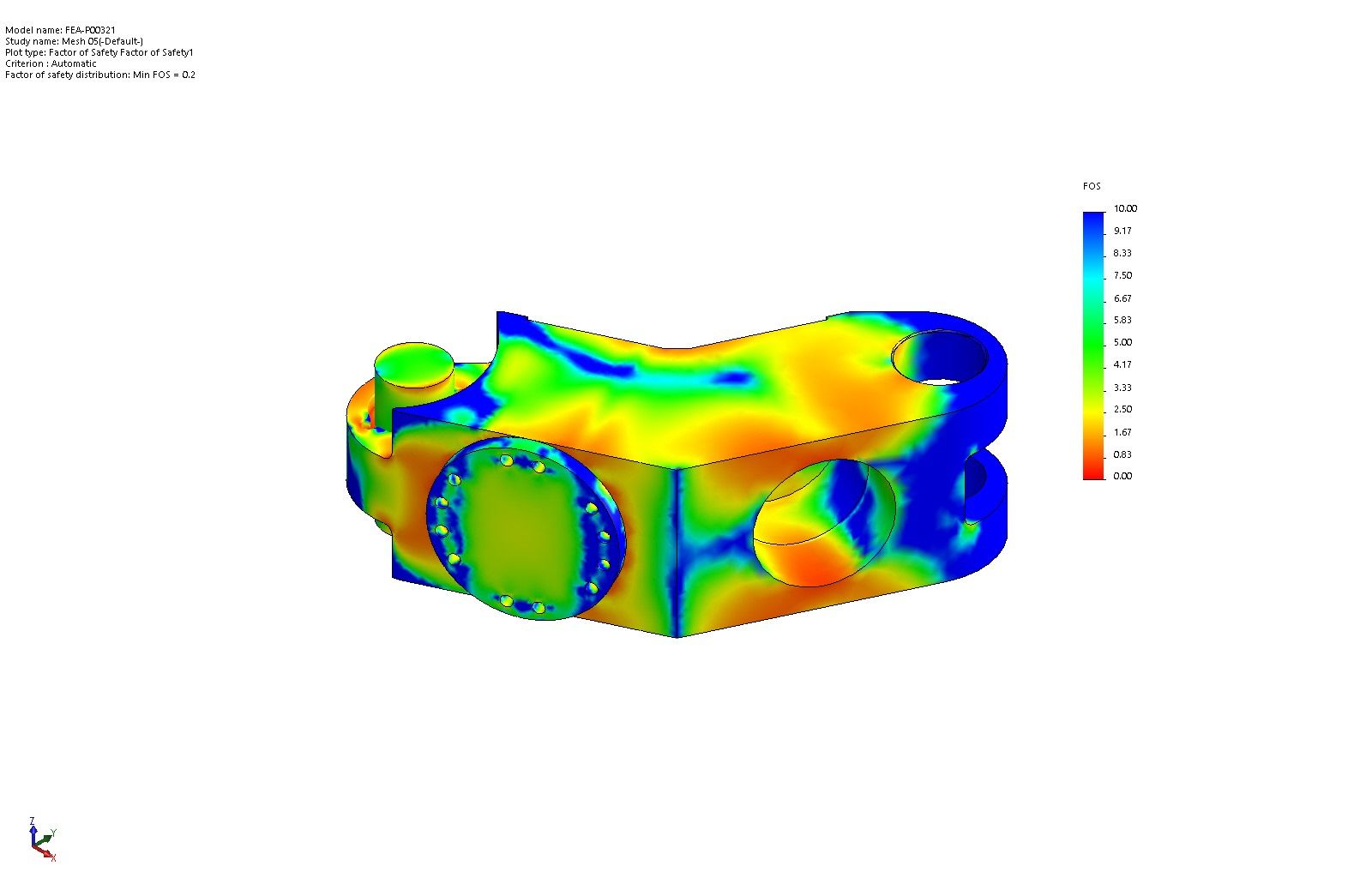
Segment of a torqueing device
This part is so complex and has so much responsibility that it took more than two weeks just to plan and prepare the workshop documentation. j
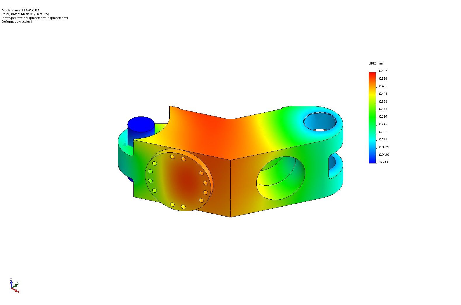
Segment of a torqueing device
Besides deformations, stresses and contact pressure had to be checked also.
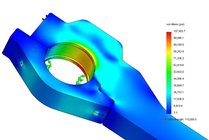
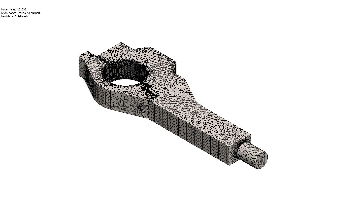
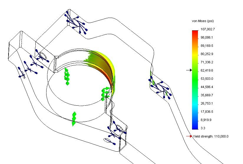
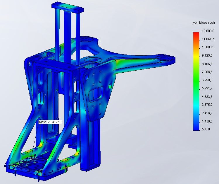
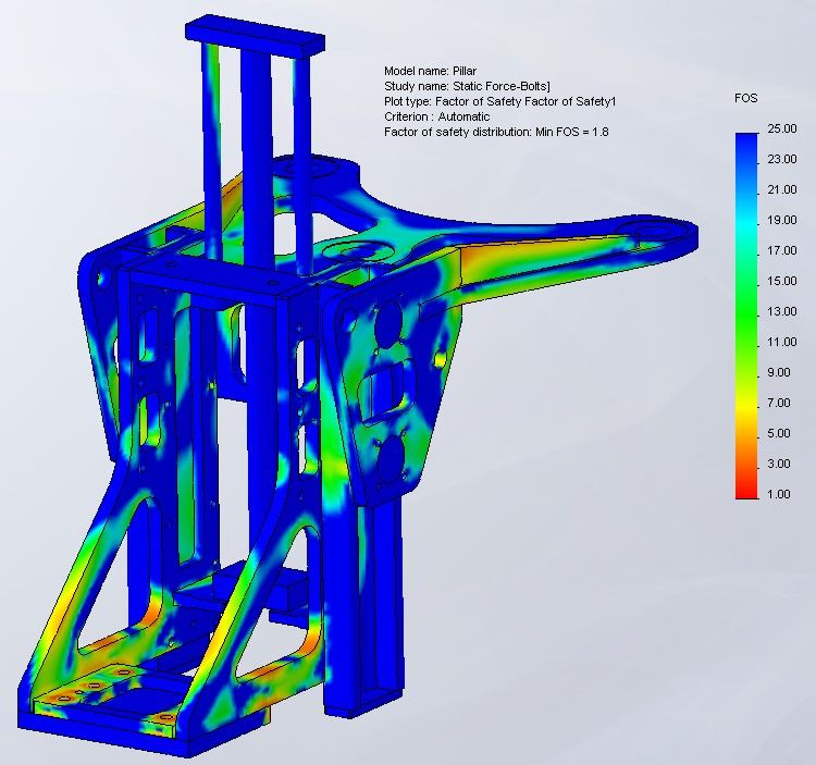

The part that the cylinder leans on which achieves the required torque
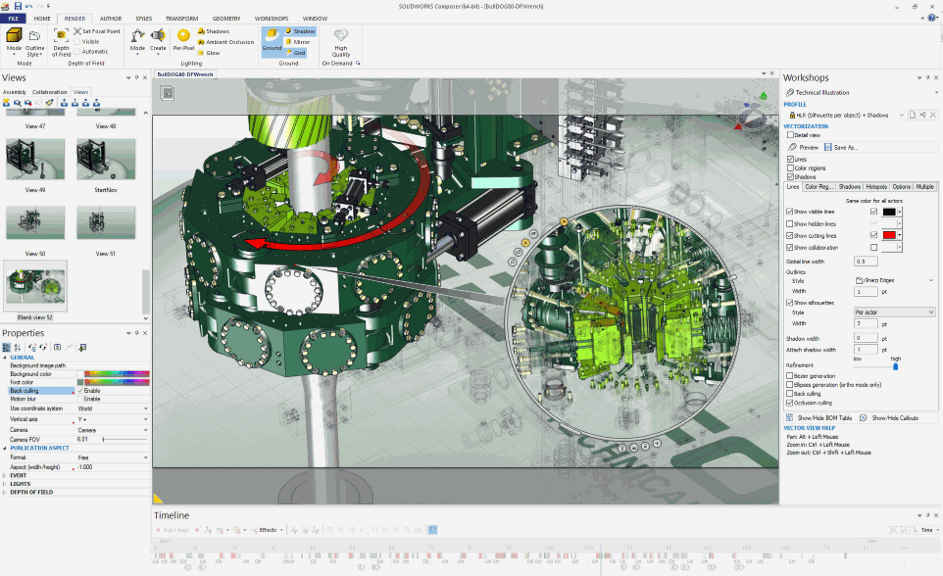
Creating instruction manuals - SolidWorks Composer
production of MARKETIng MATERIals
A special mechanism porject on a barge
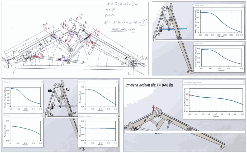
Solfins Projects