SOLIDWORKS PCB
SOLIDWORKS PCB predstavlja softversko rešenje za projektovanje elektronskih štampanih ploča. Nastao je u saradnji kompanija Altium i SolidWorks i namenjen je firmama koje razvijaju pametne IoT elektro-mehaničke proizvode.
Softver mogu koristiti i svi oni koji su navikli na Altium funkcionalnost, obzirom da su rešenja kompatibilna i dele veći deo funkcionalnosti.
Sa druge strane je omogućena bidirekciona integracija sa SOLIDWORKS 3D CAD softverom u cilju nesmetane kolaboracije elektroničara i mašinskih inženjera. ECAD-MCAD kolaboracija na SOLIDWORKS PCB platformi podiže produktivnost čitavog tima i znatno skraćuje vreme razvoja projekta i time podiže konkurentnost na najviši nivo.
SOLIDWORKS PCB is a professional software that was developed in collaboration with the team that developed Altium Designer software, through which over 20 years of ECAD experience was streamed into SOLIDWORKS PCBs with an adapted interface in accordance with the SOLIDWORKS platform, to stay consistent with the already well-known SOLIDWORKS' “quick and simple” philosophy.
PCB kao deo SolidWorks platforme
Kroz PDM i Manage software, we have a centralized team environment, a common electro-mechanical specification and tracking of projects, activities, and changes at all levels! Combined with
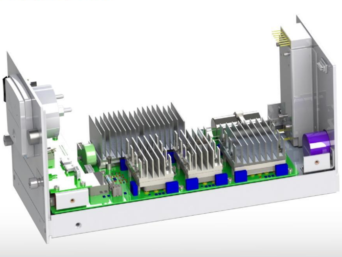
Uz kombinaciju sa SolidWorks Electrical software, you get a "digital twin" of your product in a virtual SolidWorks platform environment, over which you can run full tests,simulate how many electronis are heated or cooled, where to place passive or active cooling, how to dimension radiator orientation, and where to install ventilation openings. It is also possible to test
Moguće je testirati iwhat will happen to your device due to falls or vibrations koje se javljaju prilikom transporta.
What does SOLIDWORKS PCB solve?
The traditional approach to the development of electronic circuits, devices, and systems often has parallel and separate processes for the development of machine circuits. So far, two teams have had separate visions on one project and there have often been miscommunications. The SOLIDWORKS PCB builds a bridge between them and raises communication to the highest level. Find out how, below ...
SOLIDWORKS PCB - ECAD-MCAD communication above all
The era of new ideas has long since begun, in which the competitive factor is time. Shorter product launch times define it in the market. The time you use for development affects the future of the product. Use the potential of ECAD - MCAD collaboration with the SOLIDWORKS PCB and SOLIDWORKS platform to have your idea in 3D tomorrow and in your own hands the next day.
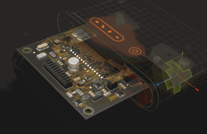
SOLIDWORKS PCB - work demonstration
SOLIDWORKS PCB - characteristics
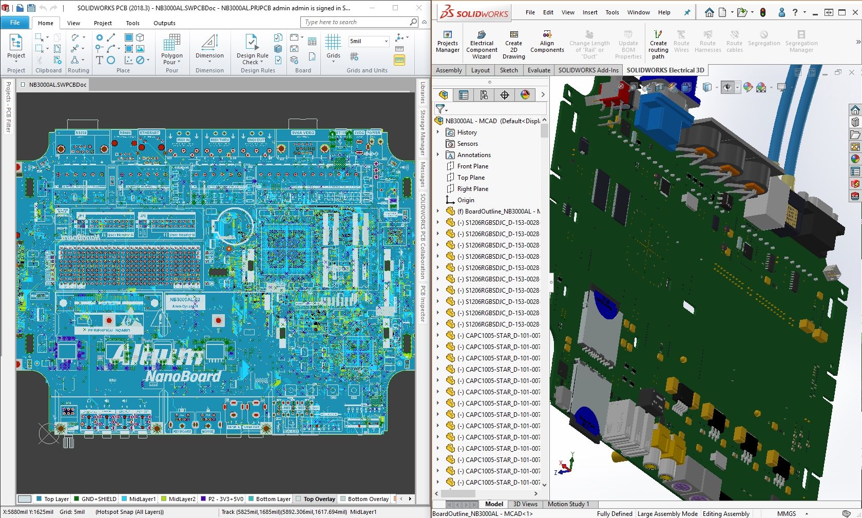
ECAD-MCAD collaboration
ECAD-MCAD collaboration on the SOLIDWORKS platform is a complete solution that enables you to develop your product in the fastest and most efficient way possible with a unified system of bi-directional information exchange on the ECAD-MCAD route.
Designing PCB printed circuit boards
Based on technology developed over 20 years by the Altium development team, SOLIDWORKS PCB has industry-wide quality approval of engine designs for PCB schematics and PCBs.
Advanced and hierarchically conceptualized schema design
Altium Designer based full functionality of advanced level schema design with hierarchical organization capability, library management and ERC (Electrical Rule Check) functionality.
A simple interface
An interface based on the SOLIDWORKS philosophy, "Quick and simple".
The managed ECAD-MCAD ECO process
The managed ECO (Engineering Change Order) process in the ECAD-MCAD collaboration between the SOLIDWORKS PCB and the SOLIDWORKS 3D CAD environment takes care of changes including the shape of the board, the positions of the electronic components, the mounting holes and the cuts of the board, thus synchronizing the design in real time.
3D real-time clearance check
Use the MCAD electronic PCB assembly to visually check the clearance of components within a 3D enclosure in real time. Doing so reduces the need for prototypes to ensure greater space utilization and integration.
Mix-mod SPICE 3f5 Simulator
SOLIDWORKS PCB enables simulations and analyses of analog circuits, as well as a mix of analog and digital circuits within a schematic editor, to detect unnecessary revisions on time and to make the right compromise when selecting components.
Online supplier search
Searching for an online supplier database, integration with a private vendor link, as well as a built-in real-time component parameter database can affect many decisions in a very short time, where cost and availability are one of the most important parameters. Define your decisions to meet requirements, budget, and delivery time.
Version Control functionality
Manage and compare all your project history and changes directly in the SOLIDWORKS PCB environment to have precise control over what changes were made, at what time, and by whom they were made.
Component parameter database
You work in a large corporate team. You need a component base with additional parameters specific to the needs of the company so that they are all synchronized in real time.
SOLIDWORKS file support
A large selection of 3D models is already available on the Internet in the SOLIDWORKS 3D CAD format. Take advantage of the huge potential of existing 3D models generated in SOLIDWORKS software to generate complete libraries, load ready-made elements and assemblies for clearance already in the SOLIDWORKS PCB environment, and many other features.
Revision management
Control the project in the development process by fully understanding revisions through comments on where and when changes occurred, through which you can make clear decisions to accept or reject the changes.
Export of all the necessary documents for the realization of your project
Automatic export of component lists (BOM), schema documents and PCB prints in 2D and 3D interpretation, production files (Gerber, Gerber X2, NC Drill, OBD ++), assembly of documents and files (pick and place, test point), validation documents (DRC - Design Rule Check, ERC - Electrical Rule Check) as well as export to STEP formats.
Altium Designer and SOLIDWORSK PCB Connector
The winning combination for your every-day work
Why choose SOLIDWORKS PCB Connector?
For users who already own Altium Designer top-level PCB design software, they need the equally powerful ECAD-MCAD collaboration tool. A platform that creates an intelligent connection as a database between Altium Designer for ECAD and SOLIDWORKS for MCAD worlds.
Get rid of stressful collaborative situations and bring your project to an end in time, with one source of truth - 3D.
SOLIDWORKS PCB - bundles
SOLIDWORKS PCB
a complete solution for making printed circuit boards
SOLIDWORKS PCB is a specialized software solution designed for the design of printed circuit boards. It contains the SOLIDWORKS PCB Connector for ECAD-MCAD collaboration with the SOLIDWORKS 3D CAD environment.
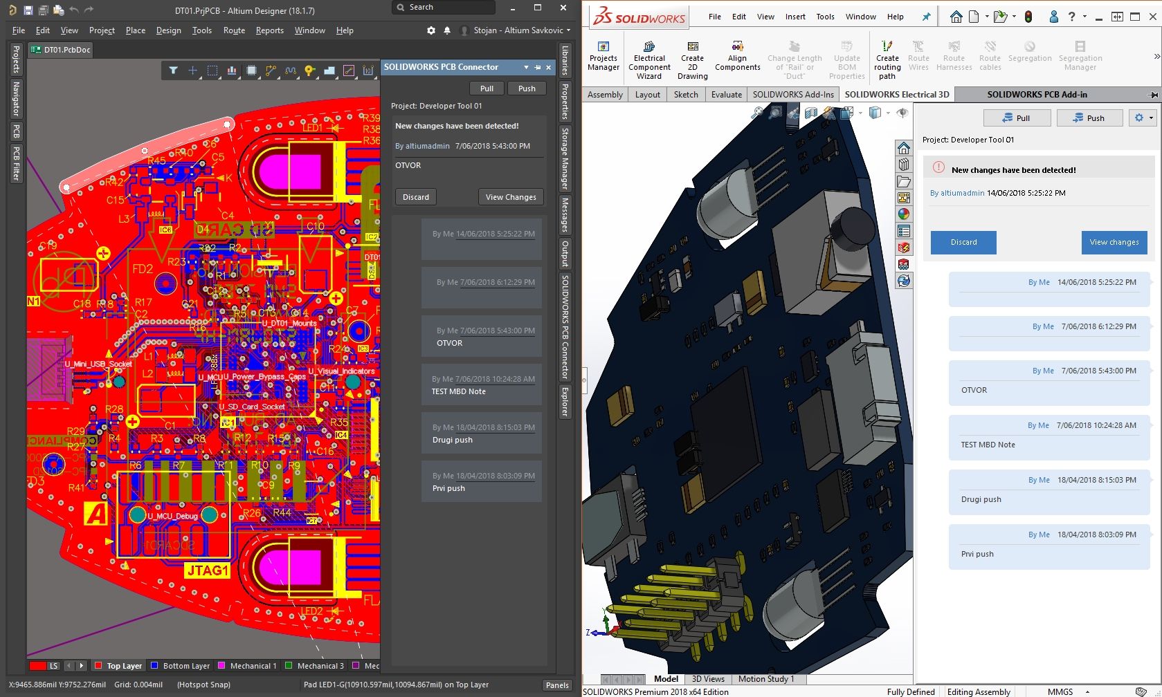
SOLIDWORKS PCB Connector for Altium Designer
collaboration for altium designer users
SOLIDWORKS PCB Connector is an add-on for Altium Designer, from where it is downloaded online. Connecting to Altium Vault / PCB Services creates a collaborative ECAD-MCAD connection to the SOLIDWORKS platform where it exists as an add-on to SOLIDWORKS 3D CAD.
Know what you need?